Cogging Compensation
Cogging compensation can be used to counteract cogging effects present in the motor by supplying an additional feedforward current. The result is a reduction of velocity ripple, mainly at lower velocities. Speeds > 500 RPM![]() "Revolutions per minute"
Is a unit of frequency of rotation: the number of full rotations completed in one minute around a fixed axis. It is used as a measure of rotational speed of a mechanical component will see diminished improvement.
"Revolutions per minute"
Is a unit of frequency of rotation: the number of full rotations completed in one minute around a fixed axis. It is used as a measure of rotational speed of a mechanical component will see diminished improvement.
This is especially useful for applications with a high demand for synchronization.
The AKD uses a cogging compensation table that stores the feedforward values to apply depending on the motors position. The table consists of 8192 entries that are evenly distributed over one revolution (rotary axis) or a range that can be specified by the user (linear axis).
The drive can also automatically detect cogging effects and generate a fitting compensation table.
Controlling Cogging Compensation
Enabling
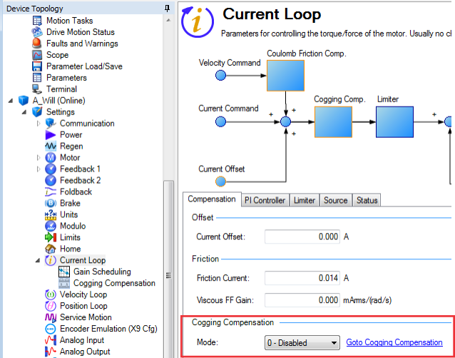
Cogging compensation can be enabled and disabled in the Compensation tab of WorkBench’s Current Loop view (see below) or using the keyword COGCOMP.EN. Enabling cogging compensation or booting the drive with Cogging compensation saved as enabled and using a non-absolute feedback while not being homed will display a warning and not apply compensation values. To clear the warning, either execute a homing procedure or deactivate Cogging compensation. If the warning is cleared by a successful homing procedure, the compensation values will be applied again.
-
- Since cogging compensation values directly translate to current supplied to the drive you should always be sure that no unusually high compensation values are stored in the table.

Cogging Compensation View
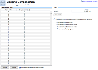
The cogging compensation view can be accessed by expanding the Current Loop item in WorkBench’s Device Topology list and selecting Cogging Compensation or by following the Goto Cogging Compensation Link in the Compensation tab of WorkBench’s Current Loop view.
The compensation table is displayed on the left. On the bottom there are buttons for importing and exporting the table from/to a csv file. Importing only works while the drive is disabled.
Controls for automatic teaching of the compensation table are displayed on the right.
Teaching (General)
The Start Teach button, or the command COGCOMP.TEACH, can be used to let the drive automatically detect cogging effects present and generate a compensation table.
The following prerequisites have to be met before starting:
- The drive has to be enabled and in Service mode and Velocity mode.
- When using a non-absolute feedback a homing has been executed.
- No other motion can be active.
If the teaching was started using the button in the Cogging Compensation view, the table will be saved to non-volatile memory and be restored after power cycling the drive. Otherwise, the table can be saved manually using COGCOMP.SAVE.
Should the motion during the teaching be stopped, either by the user or by the drive (e.g. by activating a limit switch), the teaching will be aborted, all correction values will be set to zero, and a warning will be displayed.
Tuning:
To accurately record the required torque![]() Torque is the tendency of a force to rotate an object about an axis. Just as a force is a push or a pull, a torque can be thought of as a twist to overcome cogging effects, the axis must be tuned stiff, even if the axis will not operate with high bandwidth
Torque is the tendency of a force to rotate an object about an axis. Just as a force is a push or a pull, a torque can be thought of as a twist to overcome cogging effects, the axis must be tuned stiff, even if the axis will not operate with high bandwidth![]() In computer networking, bandwidth often refers to a data rate measured in bits/s, for example, network throughput. The reason for the connection of data rate with the term bandwidth is that the limit to the data rate of a physical communication link is related to its bandwidth in hertz in production. Since the teach algorithm runs in velocity mode, please ensure the Velocity Integrator VL.KI is set high enough to achieve high stiffness while moving.
In computer networking, bandwidth often refers to a data rate measured in bits/s, for example, network throughput. The reason for the connection of data rate with the term bandwidth is that the limit to the data rate of a physical communication link is related to its bandwidth in hertz in production. Since the teach algorithm runs in velocity mode, please ensure the Velocity Integrator VL.KI is set high enough to achieve high stiffness while moving.
After teaching is complete, and cogging compensation has been achieved, the axis can be de-tuned for production operation.
Teach Steps for Rotary Motor
- Set COGCOMP.V to a low value. If the motor should move less than 2 revolutions, the range can be limited with COGCOMP.RANGEHIGH and COGCOMP.RANGELOW.
Speeds of ~1RPM are recommended, the more time the servo has to achieve perfect following error, the better quality compensation table will be achieved. - If the range is limited, the motor must be moved to a position below the value of COGCOMP.RANGELOW.
- Either click "Start Teach" from WorkBench, or issue COGCOMP.TEACH.
- When all prerequisites are met and the teaching is started the motor will move at the specified speed until it has either moved approximately 2 revolutions or when COGCOMP.RANGEHIGH and COGCOMP.RANGELOW are set and the motor has moved through this range. If cogging compensation was previously enabled, it will automatically be disabled.
Teach Steps for Linear Motor
- The linear range of the lookup table must be specified using COGCOMP.RANGELOW and COGCOMP.RANGEHIGH, the cogging compensation table will ONLY be active when the motor is within this position range.
- Set COGCOMP.V to a low value
Speeds of ~1mm/sec are recommended, the more time the servo has to achieve perfect following error, the better quality compensation table will be achieved. - Move the linear motor to a position BELOW the value set for COGCOMP.RANGELOW.
When the teach begins, positive motion will be commanded, and to ensure the full range is mapped, the motor must begin the teach below the start of the cogging table. - When all prerequisites are met and the teaching is started the motor will move at the specified speed until it has moved over the full range between COGCOMP.RANGELOW and COGCOMP.RANGEHIGH. If cogging compensation was previously enabled, it will automatically be disabled.
-
- Compensation values are tied to the position feedback of the drive. Adding or removing any offsets, homing to a different position, changing the Cogging Compensation Range or otherwise influencing the position feedback may lead to the Compensation values not matching the cogging present in the motor and thus lead to unexpected motion.
Validating Cogging Compensation
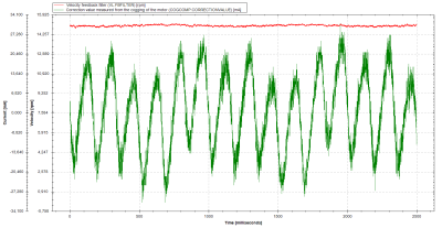
To validate the effect of cogging compensation, COGCOMP.CORRECTIONVALUE can be recorded in a scope. It shows the feedforward value that is currently applied to compensate cogging.
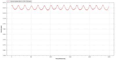
The following two images show the effect on the velocity in two scopes, the first without compensation and the second with compensation enabled and COGCOMP.CORRECTIONVALUE scoped in addition to the velocity. The same motor and tuning was used and the same motion of constant 15 RPM was commanded. The cogging compensation table used was created using automatic teaching.
Cogging compensation disabled:
Cogging compensation enabled:


